 |
416th Bombardment Group (L) WWII Maps
|
 |
Return to Table of Contents
Maps were a critical component of the successful Allied War effort during WWII.
Two organizations held primary responsibility for producing most maps for the Allied Forces -- the British Geographical Section, General Staff (GSGS) and the U.S. Army Map Service (AMS). GSGS, also known as MI 4, operated under the British Director of Military Operations and Intelligence while the AMS was part of the U.S. Army Corps of Engineers and operated under the U.S. Department of War. The Loper-Hotine Agreement, reached in May, 1942 between the GSGS and AMS, detailed the responsibilities of each organization and ensured the same, consistent maps were produced.
Many types of maps were produced for the War effort to support various needs (examples: Aeronautical and Hydrographic Charts, City Plans, Escape and Evasion, Geologic, Land Classification, Recreation, Strategic, Topographic, Transportation, etc.). Those used most frequently for Target Identification were Military Topographic Maps.
The GSGS produced numerous different Map Series, covering various geographical areas at multiple map scales. In preparation for the invasion of Sicily in 1943, the GSGS produced an illustrated guide detailing the mapping situation. As the War progressed, they produced additional guides: "Notes on the G.S.G.S. Maps of France, Belgium and Holland, December 1943" and "Notes on the G.S.G.S. Maps of Germany, Denmark and Central Europe, March 1944", ("Notes" PDF files courtesy of U.K. Defence Surveyors’ Association and McMaster University Digital Archive)
The following Map Series were used for 416th Bomb Group Target references/identifications:
References were also found in 416th BG Documents for Map Series:
Map sheets within a given Series were assigned unique Numbers or Identifiers. Most maps were also given a Name, typically a city, town or geographic feature prominent on that map sheet. While Sheet Numbers/Ids WERE unique within a Map Series, Names were not always unique.
Map sheets were produced at many different map scales to show more or less detail as required. The most common map scales included 1:25,000, 1:50,000, 1:100,000, 1:250,000, 1:500,000 and 1:1,000,000. Maps used for Target identification were typically at a scale of 1:100,000 and 1:50,000, sometimes 1:25,000.
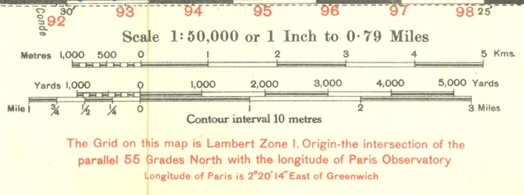
A scale such as 1:50,000 (sometimes shown as 1/50,000) defines a representative fraction (RF) or the ratio between a given distance on the map to the corresponding actual distance of the ground. For this example, one unit on the map represents 50,000 actual ground units (e.g. 1 inch on the map = 50,000 actual ground inches (almost 8/10 mile); or 1 centimeter (cm) on the map = 50,000 actual cm (500 m or 0.5 km)).
Grid Systems and Coordinates
The Supreme Headquarters Allied Expeditionary Force (S.H.A.E.F.) issued Operation Memorandum Number 9, "Map Co-ordinates" on 14 March 1944, with the object "to ensure a standard procedure for indicating a position on a map by means of grid co-ordinates and to ensure a proper use of the grid systems involved."
This Memorandum specified that "Map references will be quoted on one common system, namely that known as the British (Modified) Grid Reference System."
In the "Modified British System", each projected area (zone) is divided into Squares of 500 kilometers (km) (500,000 meters (m)) per side, each of which is designated by a lower-case letter from "a" to "z" (omitting the letter "i") from left to right starting at the top-left square. Each of these Squares is subdivided into 25 Squares of 100 kilometers (100,000 m) side which are similarly designated with upper-case letters from "A" to "Z" omitting the letter "I". These squares are again sub-divided, each into 100 squares of 10 km (10,000 m) per side. On maps of scale 1:100,000 and larger, these squares are sub-divided again into squares of 1 km (1,000 m) per side.
GSGS/AMS map legends and marginal data describe the Grid Zone and Squares. Below are extracts from the marginal data from GSGS-4250/AMS-M762 Sheet 7F-3 - "Aunay-Sur-Odon" 1:50:000 Military Topographic Map:
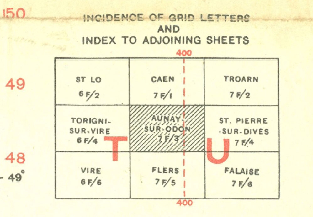
Typically, MBS Grid References used for 416th BG Mission targets specified the location to a 100 x 100 meter area, identified first by the 100 km Square letter followed by a 6 digit number. The first 3 digits defined the East-West X-Coordinate, the last 3 digits defined the North-South Y-Coordinate, to 100 meter resolution. The Grid Zone and 500 km Square letter identifier were seldom explicitly noted because they were easily identified based on the general area of the Mission.
Example Map Grid Locations

Mission 93, MBS Coordinate (LZ1) vU066447
Extracted from GSGS-4250/AMS-M762 Sheet 7F-3 - "Aunay-Sur-Odon" 1:50:000 Military Topographic Map
LZ1 = "French Lambert Zone 1"
500 km block "v", 100 km block "U"
East-West X-Coordinate "066", North-South Y-Coordinate "447"
Map shows grid lines every 1000 meters.
X-Coordinate "066" is 6/10ths of the distance from grid line "06" to "07"
Y-Coordinate "447" is 7/10ths of the distance from grid line "44" to "45"

Missions 249 and 250 MBS Coordinates (NGZ) rA315297 and (NGZ) rA305300 respectively
Extracted from GSGS-4416/AMS-M641 Sheet Q1 - "Essen" 1:100:000 Military Topographic Map
NGZ = "Nord de Guerre Zone"
500 KM block "r", 100 km block "A"
East-West X-Coordinates "315" and "305", North-South Y-Coordinates "297" and "300"
Map shows grid lines every 1000 meters.
Mission 249 X-Coordinate "315" is 5/10ths of the distance from grid line "31" to "32"
Mission 249 Y-Coordinate "297" is 7/10ths of the distance from grid line "29" to "30"
Mission 250 X-Coordinate "305" is 5/10ths of the distance from grid line "30" to "31"
Mission 250 Y-Coordinate "300" is grid line "30"
MBS Grid Zones referenced in 416th BG Missions


Left: "French Lambert Zone 1" (LZ1) - North-western part of France
Right: "Nord de Guerre Zone" (NGZ) - French, Belgian, Dutch, Luxembourg, German, Danish, Polish, Austrian, Czech, Slovak and Swiss territories
(Source: The grids used on the European Theatre of Operations)
See Also:
Combat Missions Latitude/Longitude Coordinates and Target Identifiers
WWII Map Selected References and Sources